
本文為資訊部的內訓教材,目的是讓資訊部同仁可透過Python程式來操控ESP32Cam,並思考如何應用在生活或工作上。
- ESP32Cam的安裝
- 與USB 2 TTL連接。
- 燒錄ESP32Cam
- 取得ESP32Cam的MAC address。
- 燒錄esp32cam web server程式。
- 燒錄esp32cam web server程式(AP Mode)。
- 使用Python接收ESP32Cam影像。
- 使用Thread平行處理多個ESP32Cam來源。
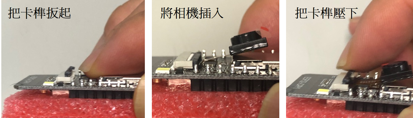
ESP32CAM安裝
剛購買的ESP32Cam,鏡頭與板子是分開的:
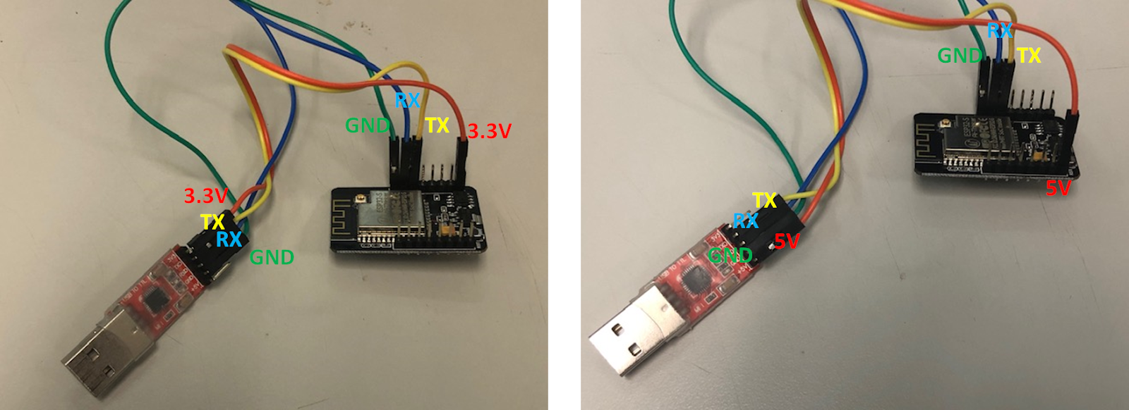
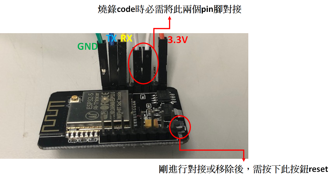
與USB to TTL連接
燒錄code必須透過USB2TTL轉接板,板子上一般都同時有3.3V及5V的輸出,而ESP32Cam可支援這兩種電壓輸入,燒錄或執行時選擇接那一種電壓皆可。
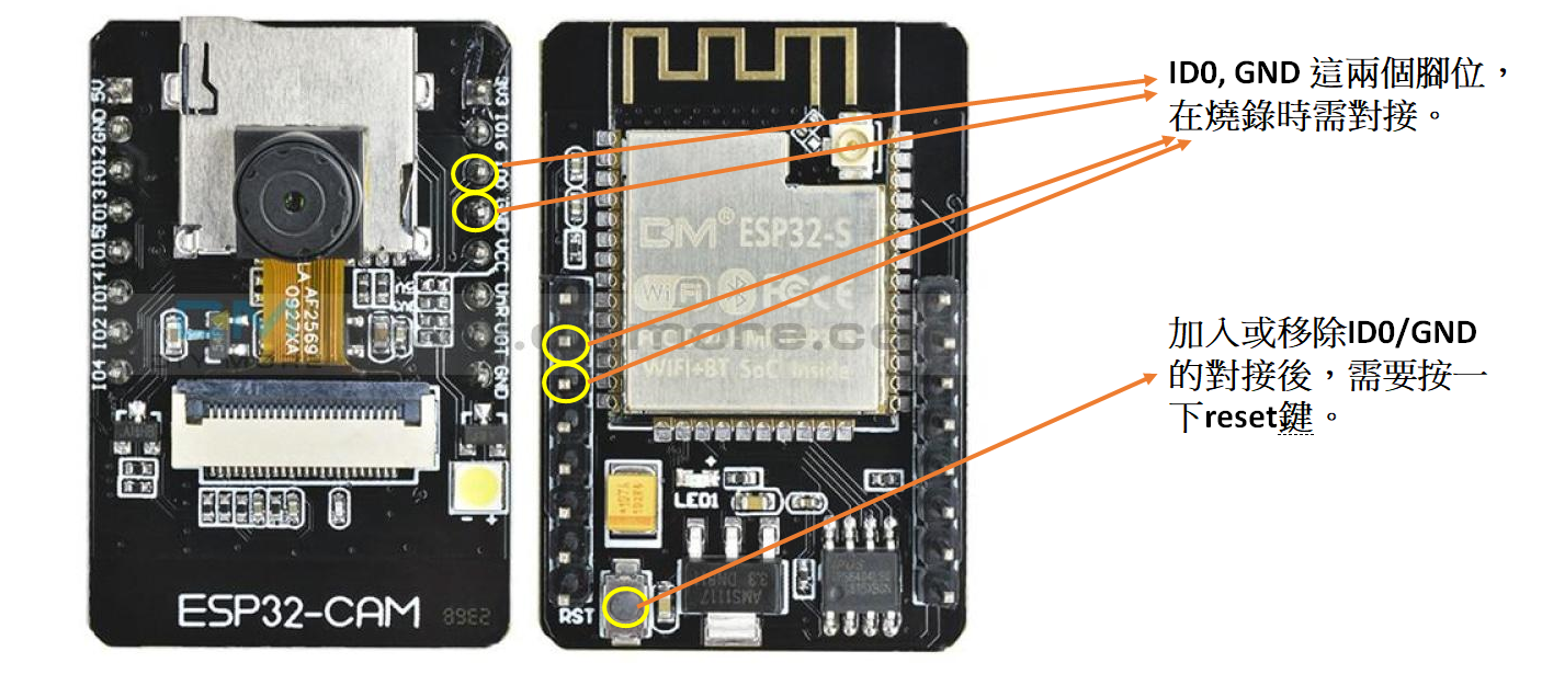
- 燒錄code時將IO0與GND對接,接著按下reset按鈕,便可開始燒錄,之後重複燒錄不需要再按reset。
- 執行模式不需要對接,在移除對接的杜邦線後也需要按一下reset按鈕,燒錄的程式才會開始執行。
- 在沒有對接IO0與GND的情況下,接上電源ESP32Cam便會自動執行燒錄的程式。
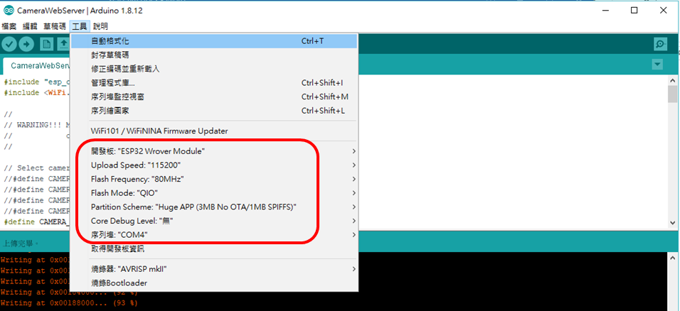
燒錄ESP32CAM
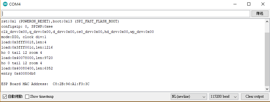
燒錄成功的訊息如下,最後一行的「Hard resetting via RTS pin…」表示燒錄完成,可移除對接後按一下reset鍵進入執行模式。
取得ESP32CAM的Mac address
有些公司使用白名單來禁止未知的mac address取得內網IP address,可避免未授權的使用者透過網路存取公司資源,因此,如果要讓內網的設備能存取到ESP32Cam,必須將ESP32Cam加到DHCP的白名單中,讓其它設備能透過網路來access該ESP32Cam。
不過要將ESP32Cam加入白名單,必須先知道mac address,我們可透過下方的Arduino程式燒錄執行後來得知:
// Complete Instructions to Get and Change ESP MAC Address: https://RandomNerdTutorials.com/get-change-esp32-esp8266-mac-address-arduino/

#ifdef ESP32
#include <WiFi.h>
#else
#include <ESP8266WiFi.h>
#endif

void setup(){
Serial.begin(115200);
Serial.println();
Serial.print("ESP Board MAC Address: ");
Serial.println(WiFi.macAddress());
}

void loop(){
}
燒錄後,移除對接並按一下reset鍵,便可在視窗中看到mac address。
燒錄esp32cam web server程式
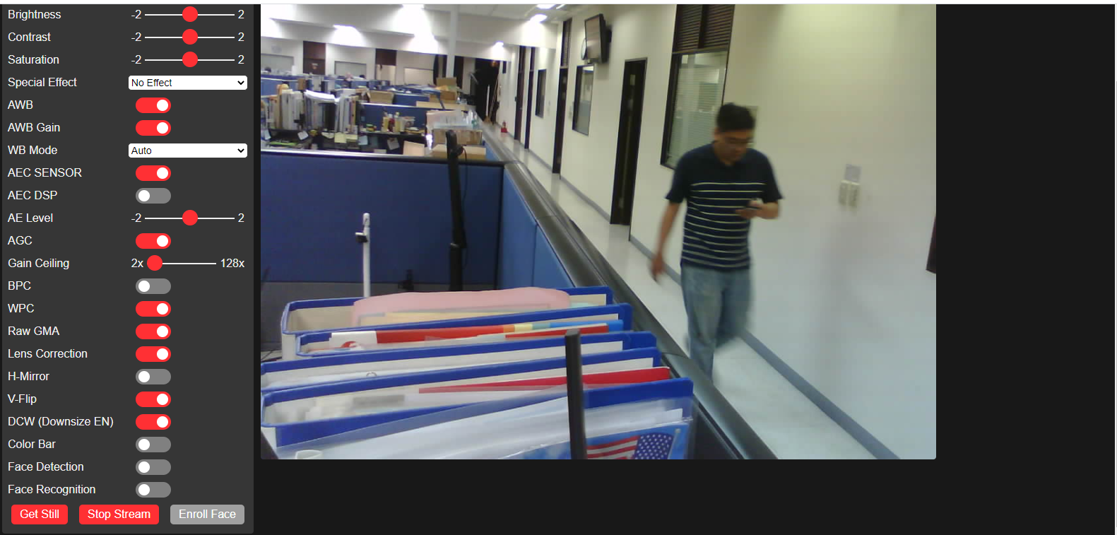
此範例程式可將ESP32Cam變成一台獨立的影像串流web主機,自動連到WIFI後提供即時的串流影像,只要透過http://{IP Address}:81/stream便可取得即時畫面(http://{IP Address}則是設定介面),但串流影像一次只能接受一個connection。程式請參考範例一。

燒錄esp32cam web server程式(AP Mode)
此範例程式除了將ESP32Cam變成一台獨立的影像串流web主機,亦將自己的WIFI設定為AP mode,亦即您不需要連上其它的WIFI AP,該ESP32Cam本身就是WIFI AP,您只要將手機或上網設備連上此WIFI AP,便能看到即時的串流影像,一樣是透過http://{IP Address}:81/stream便可取得相同的即時畫面(http://{IP Address}則是設定介面),程式請參考範例二。
使用Python接收單一ESP32Cam影像
請參考範例三,透過Python取得單一ESP32Cam的串流影像。可調整CAMERA_BUFFRER_SIZE參數值,並觀察影像的變化。
使用Python接收多支ESP32Cam影像
使用迴圈可連續的取得ESP32Cam串流畫面,但如果應用在多支ESM32Cam的情況,由於每支ESP32Cam的傳送速率及結果不同,使用單一迴圈會造成畫面凍結無法連續的情況,因此我的方式是使用multi-threads,讓每支ESP32Cam在不同的執行緒執行,再經由主程式統一搜集影像。
如下的demo所示,使用樹莓派三同時搜集四支ESP32Cam的串流影像,合併影像並進行錄影,每個camera還能保有平順的畫面,約在12fps左右。
範例一 ESP32Cam webserver from ESP32 Arduino example
#include "esp_camera.h"
#include <WiFi.h>

/* This sketch is a extension/expansion/reork of the 'official' ESP32 Camera example
sketch from Expressif:
https://github.com/espressif/arduino-esp32/tree/master/libraries/ESP32/examples/Camera/CameraWebServer

It is modified to allow control of Illumination LED Lamps's (present on some modules),
greater feedback via a status LED, and the HTML contents are present in plain text
for easy modification.

A camera name can now be configured, and wifi details can be stored in an optional
header file to allow easier updated of the repo.

The web UI has had minor changes to add the lamp control when present, I have made the
'Start Stream' controls more accessible, and add feedback of the camera name/firmware.


note: Make sure that you have either selected ESP32 AI Thinker,
or another board which has PSRAM enabled to use high resolution camera modes
*/
// Select camera board model
//#define CAMERA_MODEL_WROVER_KIT
//#define CAMERA_MODEL_ESP_EYE
//#define CAMERA_MODEL_M5STACK_PSRAM
//#define CAMERA_MODEL_M5STACK_WIDE
//#define CAMERA_MODEL_M5STACK_NO_PSRAM
#define CAMERA_MODEL_AI_THINKER

// Select camera module used on the board
#define CAMERA_MODULE_OV2640
//#define CAMERA_MODULE_OV3660

#if __has_include("myconfig.h")
// I keep my settings in a seperate header file
#include "myconfig.h"
#else
const char* ssid = "xxxxx";
const char* password = "xxxx";
#endif

// A Name for the Camera. (can be set in myconfig.h)
#ifdef CAM_NAME
char myName[] = CAM_NAME;
#else
char myName[] = "ESP32Cam_04";
#endif

// This will be displayed to identify the firmware
char myVer[] PROGMEM = __DATE__ " @ " __TIME__;


#include "camera_pins.h"

// Status and illumination LED's
#ifdef LAMP_PIN
int lampVal = 0; // Current Lamp value, range 0-100, Start off
#else
int lampVal = -1; // disable Lamp
#endif
int lampChannel = 7; // a free PWM channel (some channels used by camera)
const int pwmfreq = 50000; // 50K pwm frequency
const int pwmresolution = 9; // duty cycle bit range
// https://diarmuid.ie/blog/pwm-exponential-led-fading-on-arduino-or-other-platforms
const int pwmIntervals = 100; // The number of Steps between the output being on and off
float lampR; // The R value in the PWM graph equation (calculated in setup)

void startCameraServer();

void setup() {
Serial.begin(115200);
Serial.setDebugOutput(true);
Serial.println();
Serial.println("====");
Serial.print("esp32-cam-webserver: ");
Serial.println(myName);
Serial.print("Code Built: ");
Serial.println(myVer);

#ifdef LED_PIN // If we have a notification LED set it to output
pinMode(LED_PIN, OUTPUT);
digitalWrite(LED_PIN, LED_OFF);
#endif

#ifdef LAMP_PIN
ledcSetup(lampChannel, pwmfreq, pwmresolution); // configure LED PWM channel
ledcWrite(lampChannel, lampVal); // set initial value
ledcAttachPin(LAMP_PIN, lampChannel); // attach the GPIO pin to the channel
// Calculate the PWM scaling R factor:
// https://diarmuid.ie/blog/pwm-exponential-led-fading-on-arduino-or-other-platforms
lampR = (pwmIntervals * log10(2)) / (log10(pow(2, pwmresolution)));
#endif

camera_config_t config;
config.ledc_channel = LEDC_CHANNEL_0;
config.ledc_timer = LEDC_TIMER_0;
config.pin_d0 = Y2_GPIO_NUM;
config.pin_d1 = Y3_GPIO_NUM;
config.pin_d2 = Y4_GPIO_NUM;
config.pin_d3 = Y5_GPIO_NUM;
config.pin_d4 = Y6_GPIO_NUM;
config.pin_d5 = Y7_GPIO_NUM;
config.pin_d6 = Y8_GPIO_NUM;
config.pin_d7 = Y9_GPIO_NUM;
config.pin_xclk = XCLK_GPIO_NUM;
config.pin_pclk = PCLK_GPIO_NUM;
config.pin_vsync = VSYNC_GPIO_NUM;
config.pin_href = HREF_GPIO_NUM;
config.pin_sscb_sda = SIOD_GPIO_NUM;
config.pin_sscb_scl = SIOC_GPIO_NUM;
config.pin_pwdn = PWDN_GPIO_NUM;
config.pin_reset = RESET_GPIO_NUM;
config.xclk_freq_hz = 20000000;
config.pixel_format = PIXFORMAT_JPEG;
//init with high specs to pre-allocate larger buffers
if (psramFound()) {
config.frame_size = FRAMESIZE_UXGA;
config.jpeg_quality = 10;
config.fb_count = 2;
} else {
config.frame_size = FRAMESIZE_SVGA;
config.jpeg_quality = 12;
config.fb_count = 1;
}

#if defined(CAMERA_MODEL_ESP_EYE)
pinMode(13, INPUT_PULLUP);
pinMode(14, INPUT_PULLUP);
#endif

// camera init
esp_err_t err = esp_camera_init(&config);
if (err != ESP_OK) {
Serial.printf("Camera init failed with error 0x%x", err);
return;
}

sensor_t * s = esp_camera_sensor_get();
//initial sensors are flipped vertically and colors are a bit saturated
if (s->id.PID == OV3660_PID) {
s->set_vflip(s, 1);//flip it back
s->set_brightness(s, 1);//up the blightness just a bit
s->set_saturation(s, -2);//lower the saturation
}
//drop down frame size for higher initial frame rate
s->set_framesize(s, FRAMESIZE_SVGA);

#if defined(CAMERA_MODEL_M5STACK_WIDE)
s->set_vflip(s, 1);
s->set_hmirror(s, 1);
#endif

// Feedback that hardware init is complete and we are now attempting to connect
Serial.println("");
Serial.print("Connecting to Wifi Netowrk: ");
Serial.println(ssid);
flashLED(400);
delay(100);

WiFi.begin(ssid, password);

while (WiFi.status() != WL_CONNECTED) {
delay(250); // Wait for Wifi to connect. If this fails wifi the code basically hangs here.
// - It would be good to do something else here as a future enhancement.
// (eg: go to a captive AP config portal to configure the wifi)
}

// feedback that we are connected
Serial.println("WiFi connected");
Serial.println("");
Serial.print("ESP Board MAC Address: ");
Serial.println(WiFi.macAddress());
flashLED(200);
delay(100);
flashLED(200);
delay(100);
flashLED(200);

// Start the Stream server, and the handler processes for the Web UI.
startCameraServer();

Serial.print("Camera Ready! Use 'http://");
Serial.print(WiFi.localIP());
Serial.println("' to connect");
}

// Notification LED
void flashLED(int flashtime)
{
#ifdef LED_PIN // If we have it; flash it.
digitalWrite(LED_PIN, LED_ON); // On at full power.
delay(flashtime); // delay
digitalWrite(LED_PIN, LED_OFF); // turn Off
#else
return; // No notifcation LED, do nothing, no delay
#endif
}


void loop() {
// Just loop forever.
// The stream and URI handler processes initiated by the startCameraServer() call at the
// end of setup() will handle the camera and UI processing from now on.
delay(10000);
}
範例二 ESP32Cam web server for AP mode
(from https://randomnerdtutorials.com/esp32-cam-video-streaming-web-server-camera-home-assistant/)
/*********
Rui Santos
Complete project details at https://RandomNerdTutorials.com/esp32-cam-video-streaming-web-server-camera-home-assistant/

IMPORTANT!!!
- Select Board "AI Thinker ESP32-CAM"
- GPIO 0 must be connected to GND to upload a sketch
- After connecting GPIO 0 to GND, press the ESP32-CAM on-board RESET button to put your board in flashing mode

Permission is hereby granted, free of charge, to any person obtaining a copy
of this software and associated documentation files.
The above copyright notice and this permission notice shall be included in all
copies or substantial portions of the Software.
*********/

#include "esp_camera.h"
#include <WiFi.h>
#include "esp_timer.h"
#include "img_converters.h"
#include "Arduino.h"
#include "fb_gfx.h"
#include "soc/soc.h" //disable brownout problems
#include "soc/rtc_cntl_reg.h" //disable brownout problems
#include "esp_http_server.h"

// Replace with your network credentials
const char* ssid = "somedayumustdie";
const char* password = "ggyy78ggyy78";

#define PART_BOUNDARY "123456789000000000000987654321"

// This project was tested with the AI Thinker Model, M5STACK PSRAM Model and M5STACK WITHOUT PSRAM
#define CAMERA_MODEL_AI_THINKER
//#define CAMERA_MODEL_M5STACK_PSRAM
//#define CAMERA_MODEL_M5STACK_WITHOUT_PSRAM

// Not tested with this model
//#define CAMERA_MODEL_WROVER_KIT

#if defined(CAMERA_MODEL_WROVER_KIT)
#define PWDN_GPIO_NUM -1
#define RESET_GPIO_NUM -1
#define XCLK_GPIO_NUM 21
#define SIOD_GPIO_NUM 26
#define SIOC_GPIO_NUM 27

#define Y9_GPIO_NUM 35
#define Y8_GPIO_NUM 34
#define Y7_GPIO_NUM 39
#define Y6_GPIO_NUM 36
#define Y5_GPIO_NUM 19
#define Y4_GPIO_NUM 18
#define Y3_GPIO_NUM 5
#define Y2_GPIO_NUM 4
#define VSYNC_GPIO_NUM 25
#define HREF_GPIO_NUM 23
#define PCLK_GPIO_NUM 22

#elif defined(CAMERA_MODEL_M5STACK_PSRAM)
#define PWDN_GPIO_NUM -1
#define RESET_GPIO_NUM 15
#define XCLK_GPIO_NUM 27
#define SIOD_GPIO_NUM 25
#define SIOC_GPIO_NUM 23

#define Y9_GPIO_NUM 19
#define Y8_GPIO_NUM 36
#define Y7_GPIO_NUM 18
#define Y6_GPIO_NUM 39
#define Y5_GPIO_NUM 5
#define Y4_GPIO_NUM 34
#define Y3_GPIO_NUM 35
#define Y2_GPIO_NUM 32
#define VSYNC_GPIO_NUM 22
#define HREF_GPIO_NUM 26
#define PCLK_GPIO_NUM 21

#elif defined(CAMERA_MODEL_M5STACK_WITHOUT_PSRAM)
#define PWDN_GPIO_NUM -1
#define RESET_GPIO_NUM 15
#define XCLK_GPIO_NUM 27
#define SIOD_GPIO_NUM 25
#define SIOC_GPIO_NUM 23

#define Y9_GPIO_NUM 19
#define Y8_GPIO_NUM 36
#define Y7_GPIO_NUM 18
#define Y6_GPIO_NUM 39
#define Y5_GPIO_NUM 5
#define Y4_GPIO_NUM 34
#define Y3_GPIO_NUM 35
#define Y2_GPIO_NUM 17
#define VSYNC_GPIO_NUM 22
#define HREF_GPIO_NUM 26
#define PCLK_GPIO_NUM 21

#elif defined(CAMERA_MODEL_AI_THINKER)
#define PWDN_GPIO_NUM 32
#define RESET_GPIO_NUM -1
#define XCLK_GPIO_NUM 0
#define SIOD_GPIO_NUM 26
#define SIOC_GPIO_NUM 27

#define Y9_GPIO_NUM 35
#define Y8_GPIO_NUM 34
#define Y7_GPIO_NUM 39
#define Y6_GPIO_NUM 36
#define Y5_GPIO_NUM 21
#define Y4_GPIO_NUM 19
#define Y3_GPIO_NUM 18
#define Y2_GPIO_NUM 5
#define VSYNC_GPIO_NUM 25
#define HREF_GPIO_NUM 23
#define PCLK_GPIO_NUM 22
#else
#error "Camera model not selected"
#endif

static const char* _STREAM_CONTENT_TYPE = "multipart/x-mixed-replace;boundary=" PART_BOUNDARY;
static const char* _STREAM_BOUNDARY = "\r\n--" PART_BOUNDARY "\r\n";
static const char* _STREAM_PART = "Content-Type: image/jpeg\r\nContent-Length: %u\r\n\r\n";

httpd_handle_t stream_httpd = NULL;

static esp_err_t stream_handler(httpd_req_t *req){
camera_fb_t * fb = NULL;
esp_err_t res = ESP_OK;
size_t _jpg_buf_len = 0;
uint8_t * _jpg_buf = NULL;
char * part_buf[64];

res = httpd_resp_set_type(req, _STREAM_CONTENT_TYPE);
if(res != ESP_OK){
return res;
}

while(true){
fb = esp_camera_fb_get();
if (!fb) {
Serial.println("Camera capture failed");
res = ESP_FAIL;
} else {
if(fb->width > 400){
if(fb->format != PIXFORMAT_JPEG){
bool jpeg_converted = frame2jpg(fb, 80, &_jpg_buf, &_jpg_buf_len);
esp_camera_fb_return(fb);
fb = NULL;
if(!jpeg_converted){
Serial.println("JPEG compression failed");
res = ESP_FAIL;
}
} else {
_jpg_buf_len = fb->len;
_jpg_buf = fb->buf;
}
}
}
if(res == ESP_OK){
size_t hlen = snprintf((char *)part_buf, 64, _STREAM_PART, _jpg_buf_len);
res = httpd_resp_send_chunk(req, (const char *)part_buf, hlen);
}
if(res == ESP_OK){
res = httpd_resp_send_chunk(req, (const char *)_jpg_buf, _jpg_buf_len);
}
if(res == ESP_OK){
res = httpd_resp_send_chunk(req, _STREAM_BOUNDARY, strlen(_STREAM_BOUNDARY));
}
if(fb){
esp_camera_fb_return(fb);
fb = NULL;
_jpg_buf = NULL;
} else if(_jpg_buf){
free(_jpg_buf);
_jpg_buf = NULL;
}
if(res != ESP_OK){
break;
}
//Serial.printf("MJPG: %uB\n",(uint32_t)(_jpg_buf_len));
}
return res;
}

void startCameraServer(){
httpd_config_t config = HTTPD_DEFAULT_CONFIG();
config.server_port = 80;

httpd_uri_t index_uri = {
.uri = "/",
.method = HTTP_GET,
.handler = stream_handler,
.user_ctx = NULL
};

//Serial.printf("Starting web server on port: '%d'\n", config.server_port);
if (httpd_start(&stream_httpd, &config) == ESP_OK) {
httpd_register_uri_handler(stream_httpd, &index_uri);
}
}

void setup() {
WRITE_PERI_REG(RTC_CNTL_BROWN_OUT_REG, 0); //disable brownout detector

Serial.begin(115200);
Serial.setDebugOutput(false);

camera_config_t config;
config.ledc_channel = LEDC_CHANNEL_0;
config.ledc_timer = LEDC_TIMER_0;
config.pin_d0 = Y2_GPIO_NUM;
config.pin_d1 = Y3_GPIO_NUM;
config.pin_d2 = Y4_GPIO_NUM;
config.pin_d3 = Y5_GPIO_NUM;
config.pin_d4 = Y6_GPIO_NUM;
config.pin_d5 = Y7_GPIO_NUM;
config.pin_d6 = Y8_GPIO_NUM;
config.pin_d7 = Y9_GPIO_NUM;
config.pin_xclk = XCLK_GPIO_NUM;
config.pin_pclk = PCLK_GPIO_NUM;
config.pin_vsync = VSYNC_GPIO_NUM;
config.pin_href = HREF_GPIO_NUM;
config.pin_sscb_sda = SIOD_GPIO_NUM;
config.pin_sscb_scl = SIOC_GPIO_NUM;
config.pin_pwdn = PWDN_GPIO_NUM;
config.pin_reset = RESET_GPIO_NUM;
config.xclk_freq_hz = 20000000;
config.pixel_format = PIXFORMAT_JPEG;

if(psramFound()){
config.frame_size = FRAMESIZE_UXGA;
config.jpeg_quality = 10;
config.fb_count = 2;
} else {
config.frame_size = FRAMESIZE_SVGA;
config.jpeg_quality = 12;
config.fb_count = 1;
}

// Camera init
esp_err_t err = esp_camera_init(&config);
if (err != ESP_OK) {
Serial.printf("Camera init failed with error 0x%x", err);
return;
}
// Connect to Wi-Fi network with SSID and password
Serial.print("Setting AP (Access Point)…");
// Remove the password parameter, if you want the AP (Access Point) to be open
WiFi.softAP(ssid, password);

IPAddress IP = WiFi.softAPIP();
Serial.print("Camera Stream Ready!GGYYGGYY Connect to the ESP32 AP and go to: http://");
Serial.println(IP);

// Start streaming web server
startCameraServer();
}

void loop() {
delay(1);
}
範例三 接收單一ESP32Cam的串流影像
# -*- coding: UTF-8 -*-
from urllib.request import urlopen
import imutils
import numpy as np
import cv2

url = 'http://172.30.17.165:81/stream'
fix_size = (320,240)
CAMERA_BUFFRER_SIZE = 1200
rotate = 180
bts=b''

def read_stream(stm):
global bts

bts+=stm.read(CAMERA_BUFFRER_SIZE)
jpghead=bts.find(b'\xff\xd8')
jpgend=bts.find(b'\xff\xd9')

if jpghead>-1 and jpgend>-1:
jpg=bts[jpghead:jpgend+2]
bts=bts[jpgend+2:]

try:
img=cv2.imdecode(np.frombuffer(jpg,dtype=np.uint8),cv2.IMREAD_UNCHANGED)
height,width=img.shape[:2]
img=cv2.resize(img,(fix_size[0], fix_size[1]))
except:
img = None
print("no data received.")

return img,(width,height), bts

if __name__ == "__main__":
stream = urlopen(url)

while True:
img, (width, height), bts = read_stream(stream)

if img is not None:
if(rotate != 0):
img = imutils.rotate(img, rotate)

cv2.imshow("TEST", img)
cv2.waitKey(1)
